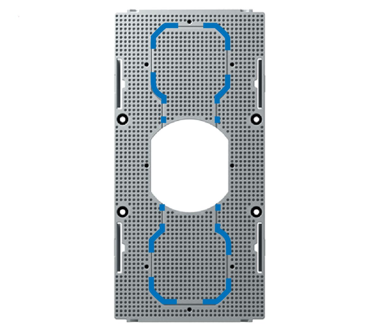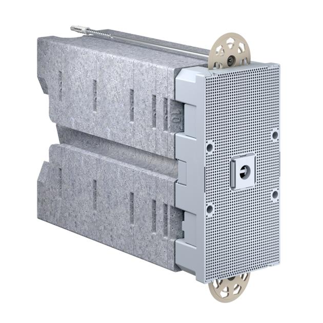


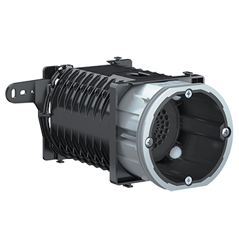
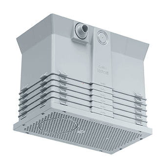


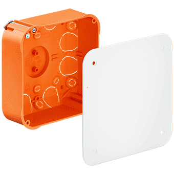
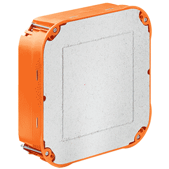
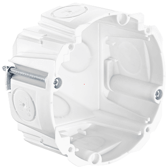
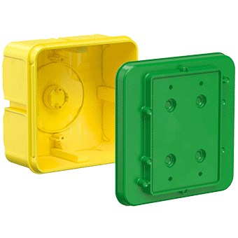


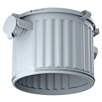
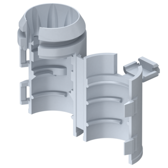
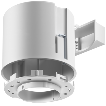

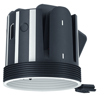
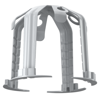


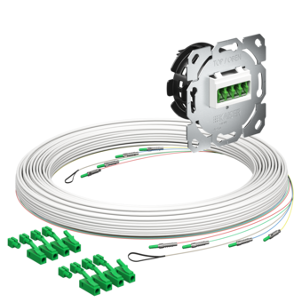


System equipment carrier
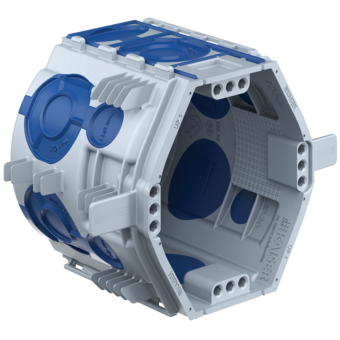
System equipment carrier 240 - 310 mm with multiple accessory insert for boxes

- Article no: 9966.32
- EAN: 7611614269627

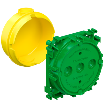
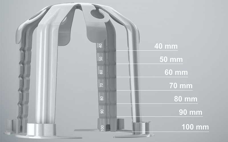
- Adaptation to insulation thickness possible in 10 mm steps
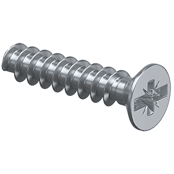
- Including 2 screw dowels
- Material: Polyethylene
- Insulation material: Neopor
- Processing temperature: - 5 °C / + 60 °C
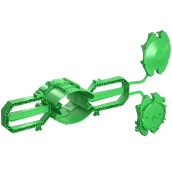
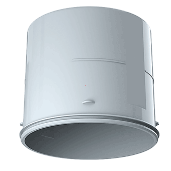
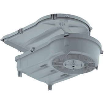
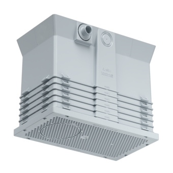
System equipment carrier
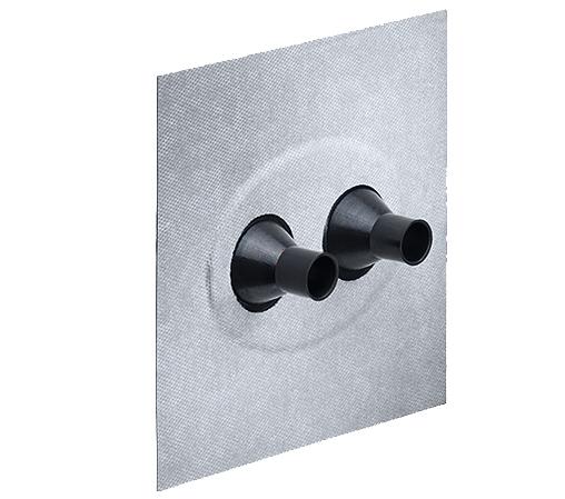
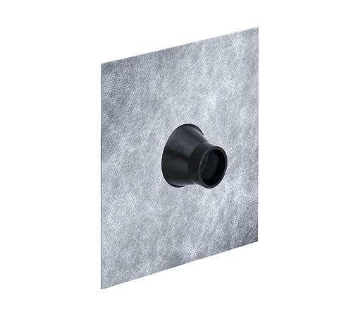
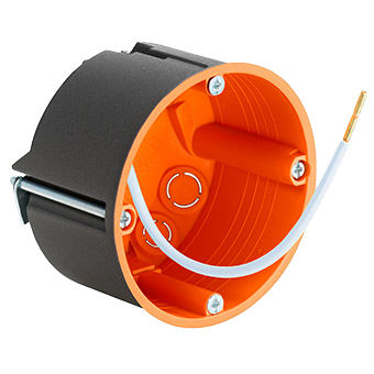
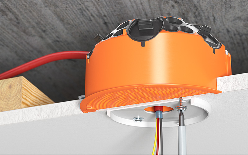
The system equipment carrier is designed to fit perfectly into the external insulation and, in this way, reliably prevents heat bridges. Fast, easy fixing using the screw dowels included in the scope of delivery permanently anchors the equipment carrier securely to many surfaces. Ideal for stable fixing of external lamps, sockets, door intercom devices, and many more. In doing so, high weight-bearing loads are not a problem.
- Extra-fast, easy installation
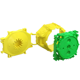
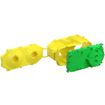
- Two product types allow a wide range of applications
- Heat bridges are efficiently prevented
- Adaptable to insulation thickness in 10 mm steps – no cutting necessary
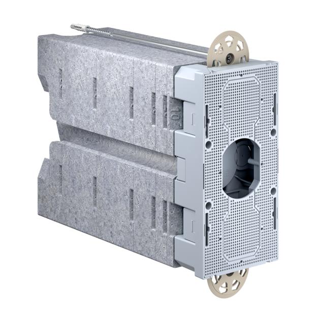
- Modular design for insulation thicknesses from 160 to 310 mm

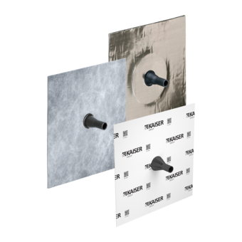
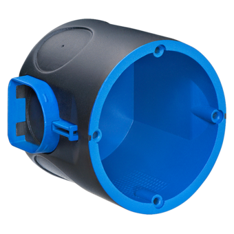
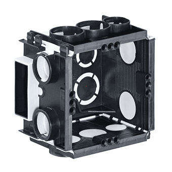
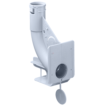
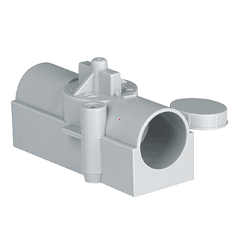
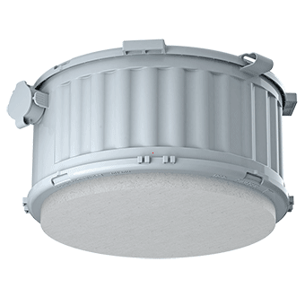
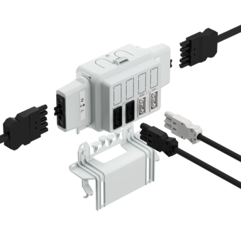
Application examples


Heat bridge calculation
A heat bridge calculation carried out by the Passivhaus Institut in Darmstadt shows that the system equipment carrier has a point-specific heat bridge loss coefficient of xWB < 0,01 W/K and meets the requirements of a heat bridge-free facade.

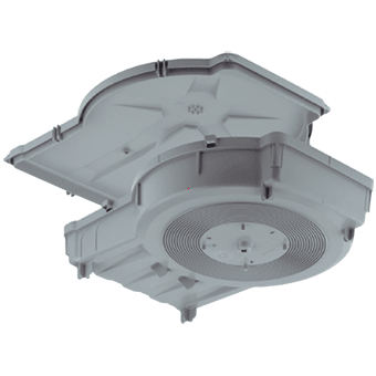
Weight-bearing loads

1 Weight-bearing loads – independently of the insulation thickness: For an overhang of 160 mm and insulation thicknesses of 160 - 310 mm; 8 kg without additional screwing of the front plate; 10 kg with additional screwing of the front plate. The system equipment carrier must be fitted vertically. The hole for the dowel must be drilled to make an exact fit. | 2 Increasing the weight-bearing loads: To fix heavier loads, we recommend additional securing of the mounting plate by means of four Ø 3.5 x 25 screws